Industrial power supplies are the unsung heroes of factories, labs, and server rooms: they sit quietly, turn brutal wall power into
clean DC, and only get attention when something goes wrong. Which is why a faulty industrial 960 watt power supply
can be extra confusing when you discover it contains a very efficient APFC circuit. It’s like opening a car with a
world-class engine… and realizing the key fob is dead.
In this deep dive, we’ll unpack what Active Power Factor Correction (APFC) really does, how “very efficient” APFC
is achieved in modern ~1 kW designs, and why a supply can still fail even if its APFC stage is built like an honor student. We’ll keep it
practical, a little funny, and firmly on the safe side: high-voltage power electronics are not the place to wing it.
First: What APFC Is (And Why Industry Cares)
If you’ve ever heard someone describe a power supply as “nice to the grid,” they’re usually talking about power factor and harmonics.
Many AC-to-DC converters naturally draw current in short, ugly gulps instead of a smooth sine-like shape. That wastes capacity in wiring,
transformers, and generators, and it can push harmonic distortion higher than regulators and power-quality folks prefer.
APFC fixes this by using a switching pre-regulator that shapes the input current so it more closely follows the input
voltage waveform. In plain English: instead of sipping politely, the supply stops chugging from the wall like it’s speedrunning a smoothie.
Why APFC shows up in a 960 W industrial supply
- Compliance pressure: Harmonic emission limits and power-quality expectations are a big deal in professional equipment.
- Lower stress on infrastructure: Better power factor can reduce losses and heating in upstream distribution.
- Efficiency and thermal sanity: A well-designed front end can reduce wasted power and help hit premium efficiency tiers.
- Universal input friendliness: Many industrial supplies must behave across wide input ranges and still deliver near-rated power.
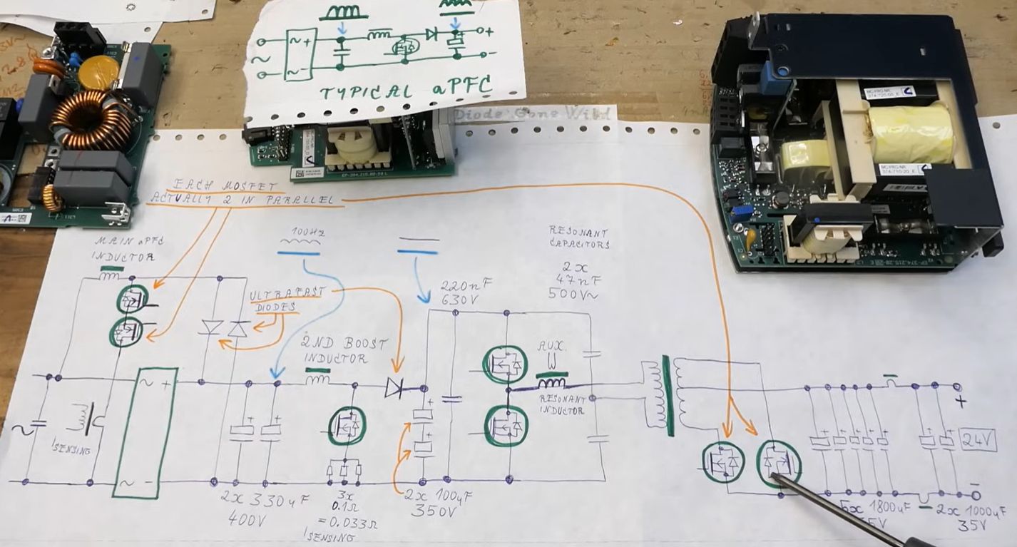
Anatomy of a Typical 960 W Industrial AC-DC Power Supply
While layouts vary, many high-power industrial supplies follow a familiar block diagram:
- EMI input filter: Keeps switching noise from escaping back to the mains and helps the product play nicely with EMC rules.
- Rectification: Turns AC into DC (usually via a diode bridge in classic designs).
- APFC stage: Commonly a boost-type PFC that creates a regulated high-voltage DC bus and shapes input current.
- Isolated DC/DC stage: Often LLC resonant or phase-shifted full bridge for high efficiency at high power.
- Secondary regulation and protection: Feedback, OCP/OVP/OTP protections, plus housekeeping rails for control logic and fans.
When people say, “The APFC is efficient,” they’re typically praising that front-end stage: its controller strategy, switching devices,
magnetics, and how well it minimizes conduction and switching losses while keeping current waveforms clean.
What Makes an APFC Circuit “Very Efficient”?
Efficiency at ~1 kW isn’t magicit’s an organized reduction of losses, plus careful control of EMI and thermals. Here are the big levers
designers pull to make APFC both clean and stingy with watts.
1) The topology choice: boost PFC (and its smarter cousins)
The classic workhorse is the boost PFC. It’s popular because it scales well, it’s well understood, and it can achieve
near-unity power factor with good control. But “very efficient” designs often go further:
- Interleaved boost PFC: Two (or more) PFC channels operate out of phase, reducing ripple current and spreading heat.
- Totem-pole PFC: A newer approach (common in high-efficiency platforms) that can reduce diode losses and improve efficiency,
especially with modern fast switches (e.g., SiC or high-performance MOSFETs).
In practice, if a 960 W supply is bragging-worthy, it may use interleaving or a modern PFC approach to reduce losses and meet tougher
efficiency expectations.
2) Control mode: CCM, CrCM, and why it matters
PFC controllers operate in different modes depending on power level and goals:
- CCM (Continuous Conduction Mode): Great for higher power; tends to keep current flowing more continuously, which can reduce peak currents and improve efficiency.
- CrCM/BCM (Critical/Boundary Conduction Mode): Popular for simpler designs and certain efficiency/EMI tradeoffs; switching happens near zero current in the inductor, which can reduce switching losses.
High-power industrial supplies frequently lean toward approaches that keep conduction losses manageable and reduce ripple that would otherwise
demand larger magnetics and filters.
3) Component choices that quietly win the efficiency war
- Lower-loss switches: Reduced RDS(on) and optimized gate drive can cut heat dramatically at high power.
- Better magnetics: PFC inductors designed for lower core loss at the chosen switching frequency can be the difference between “warm” and “why is the chassis cooking?”
- Smarter rectification strategy: Reducing diode losses (where applicable) is a classic efficiency upgrade, especially at high current.
- Layout and noise control: Efficient designs often fail if the layout is sloppy; parasitics can turn clean switching into a noisy mess and force designers to add lossier “band-aids.”
4) Efficiency isn’t just a numberit’s behavior across line and load
Industrial supplies rarely live at exactly 50% load in a climate-controlled paradise. A truly good APFC stage stays stable and efficient
across:
- Wide input ranges (brownouts, high line, generator power)
- Load steps (motors, actuators, automation cycles)
- Temperature swings (sealed cabinets, dusty environments, 24/7 operation)
This is why many serious platforms lean on industry test methodologies and certification programs to validate efficiency and protections
under controlled conditions.
So… How Can the Supply Be Faulty If the APFC Is Great?
Because a power supply is an ecosystem. An APFC stage can be excellent and still be trapped in a failing system like a gourmet chef working
in a kitchen where the fridge is broken.
Common “not-the-APFC” failure culprits in a 960 W industrial PSU
- Startup/housekeeping power issues: Many supplies rely on a small auxiliary converter to power control ICs, fans, and logic. If that rail is unstable, nothing else behaves.
- Protection latch events: Over-temperature, over-current, or under-voltage lockouts can shut the system down even when the PFC stage is capable of operating.
- Aging capacitors: High ripple current and heat accelerate wear. A supply can become “faulty” via increased ripple, poor hold-up, or unstable regulation long before it fully dies.
- Thermal stress and solder fatigue: Industrial environments and repeated thermal cycling can create intermittent failures that look like ghosts.
- Fan failures and airflow problems: The APFC may be efficient, but if airflow collapses, thermals win. Protection circuits will do their job: shut things down.
- Downstream DC/DC stage failure: If the isolated converter stage can’t start or regulate, the system may never reach “normal operation,” even though APFC is ready and waiting.
There’s also a special category of failure that feels personal: “It works on the bench but fails in the cabinet.”
That often points to environmental or system-level conditionsheat, vibration, input quality, grounding, or load transientsthat don’t
show up in quick tests.
Clues You Can Observe Safely (Without Becoming a Science Experiment)
A 960 W AC-DC supply contains hazardous voltages and stored energy. If you’re not trained and equipped for mains power electronics,
don’t open it. But you can still learn a lot from safe, external observations:
1) What does “faulty” look like from the outside?
- No start: No indicator LED, no fan spin (if it should spin), no output.
- Start–stop cycling: The supply attempts to start, then shuts down repeatedly (often a protection response).
- Trips upstream protection: Breaker or fuse behavior can hint at inrush or internal short conditionswithout guessing the internal cause.
- Output present but unstable: Devices reset, motors chatter, controllers brown out.
- Temperature pattern changes: “It used to run warm; now it runs hot,” can be an early reliability signal.
2) Why a highly efficient APFC stage can still “look bad” in system symptoms
APFC primarily shapes input current and regulates the high-voltage DC bus. If downstream stages are failing, you may still see odd behavior:
startup hiccups, audible switching changes, or protection cycling. That doesn’t mean the APFC is the villainit may simply be reacting
properly to conditions created elsewhere.
How Professionals Evaluate a High-Power Supply (Big-Picture View)
When a lab or qualified technician evaluates a high-power supply, the approach is structured and instrument-heavy. Think: controlled loads,
power analyzers, thermal monitoring, and repeatability. The goal isn’t “poke it until it confesses,” it’s “measure it until it tells the truth.”
- Power quality and input behavior: power factor, current harmonics, and how the supply behaves at low and high line.
- Efficiency mapping: not just one numberefficiency at multiple load points and temperatures.
- Protection verification: confirming that OCP/OVP/OTP behave predictably (and aren’t falsely triggering).
- Thermal validation: identifying hotspots, airflow issues, and component stress under real load.
This is also why power supply review methodologies and certification programs matter: they standardize the boring parts, so engineers can
argue about the interesting parts (like ripple, transient response, and whether that fan curve is secretly powered by spite).
Design Lessons: Getting Efficiency Without Fragility
A “very efficient APFC circuit” is an achievement, but it’s only one chapter in the reliability story. In industrial gear, the best designs
balance efficiency, robustness, and serviceability.
Efficiency + reliability habits you see in strong industrial platforms
- Thermal headroom: components run below their limits, because “it barely survives” is not a business model.
- Input surge and inrush management: thoughtful limiting prevents nuisance trips and reduces stress on components and upstream protection.
- EMI and layout discipline: clean switching reduces the need for lossy filtering and helps long-term stability.
- Protection that’s firm but fair: shutdowns should be predictable and recoverable when appropriate, not random.
- Quality validation: load-step testing, thermal cycling, and power-quality evaluation are where weak designs get exposed.
FAQ: Quick Answers About APFC in High-Power Industrial Supplies
Is APFC the same thing as “high efficiency”?
Not exactly. APFC improves power factor and reduces harmonics, and it can be designed efficiently. But total PSU efficiency also depends heavily on the isolated DC/DC stage,
secondary rectification, magnetics, thermal design, and control strategy.
Does a better power factor always lower your electric bill?
For many residential customers, power factor isn’t billed directly. In commercial/industrial settings, policies vary, and low power factor can contribute to penalties or
infrastructure strain. Either way, better PF generally improves how politely your equipment interacts with the power system.
Why do high-power supplies often use interleaved PFC?
Interleaving spreads current across channels, reduces ripple, improves thermal distribution, and can make EMI filtering easieruseful benefits when you’re pushing toward 1 kW and beyond.
If the APFC is efficient, what fails most often?
In real deployments, failures are frequently driven by heat, aging capacitors, fan/airflow issues, environmental stress, or problems in startup/auxiliary railsoften more than the APFC itself.
Experience Section: What “Very Efficient APFC” Feels Like in the Real World (About )
Engineers and technicians who work around high-power industrial supplies tend to develop a weird sixth sense for “good” APFCnot because they can smell power factor (please don’t try),
but because efficient APFC changes the whole personality of a system.
One common story starts with a facility that upgrades from older, rougher supplies to newer high-efficiency models. Suddenly the upstream distribution gear runs a little cooler, nuisance trips
become less frequent, and the input current stops looking like it’s biting chunks out of the sine wave. The supply doesn’t “feel” dramatic; it feels boringin the best way.
Boring power is premium power.
Another classic experience is the “it’s dead, but it’s not dead” moment. A 960 watt unit comes in labeled FAULTYoften with the same conviction people use when declaring a laptop
“broken forever” because it needs charging. In controlled testing, the APFC stage behaves beautifully: power factor is strong, harmonics are low, and the front end looks stable.
But the supply still refuses to deliver stable output in the real installation. That’s when the detective work shifts away from “is the APFC good?” to “what’s the system asking this supply to endure?”
In industrial cabinets, the answer is frequently heat and airflow. Efficient APFC reduces losses, but it doesn’t eliminate themat high power, even small percentages become real heat.
If a fan is tired, a filter is clogged, or the supply is mounted in a hot zone, protection circuits may cycle the unit off to prevent damage. From the outside, it looks like a flaky supply.
From the inside, it’s a responsible adult setting boundaries.
Then there’s the “generator day” experience. Facilities that run on backup generators sometimes discover that not all input power is created equal.
A well-designed APFC stage can be surprisingly tolerant, but some combinations of generator regulation, load steps, and wiring can create conditions where the supply enters protective behavior.
The efficient APFC isn’t necessarily failingit’s responding to input quality that’s less “utility-grade” and more “close enough, probably.”
Finally, there’s the humbling lesson many teams learn once: an APFC stage can be an A+ student, but the supply is still a group project. A weak auxiliary rail, a stressed capacitor bank,
or a marginal downstream converter can turn the whole unit into a drama series. The best “experience-based” takeaway is also the simplest:
judge the power supply as a system. Efficient APFC is a huge advantage, but reliability is the sum of thermal design, protections, components, layout discipline, and real-world validation.
In other words, the APFC can be the valedictorianand the power supply can still miss the bus.
Conclusion
A very efficient APFC circuit in a faulty industrial 960 watt power supply isn’t a contradictionit’s a reminder.
APFC is a major piece of modern high-power AC-DC design, shaping input current, supporting compliance, and helping efficiency goals. But a power supply’s reliability depends on the whole chain:
startup power, protections, thermals, airflow, downstream conversion, and the environment it lives in. If you’re evaluating a failing unit, the smartest move is to treat it as a system-level problem
and rely on qualified testing practicesbecause the watts are high, the voltages are hazardous, and the “guess-and-check” method belongs in baking cookies, not in mains electronics.